Tag Archives: wing design

2000: MY PRIVATE STORY OF THE DAVIS WING IV


click to see pdf file of Davis patent


David R. Davis, the inventor
Isaac M. Laddon, Director of Engineering
Major Reuben Hollis Fleet, Founder/Owner of Consolidated

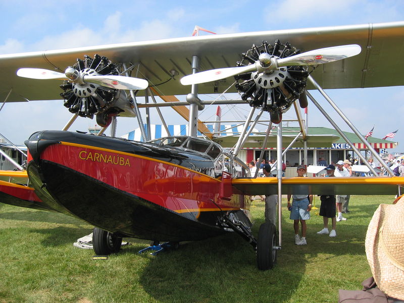
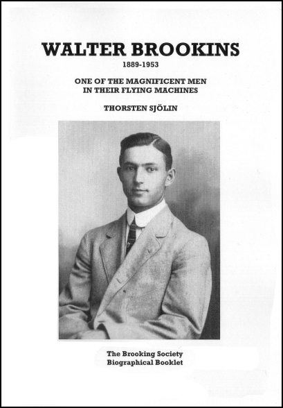
In 1937 the well known first licensed pilot of America, Walter Brookins, introduced our inventor David Davis to Reuben Fleet, the founder/owner of the Consolidated Aircraft Corporation in San Diego, California.

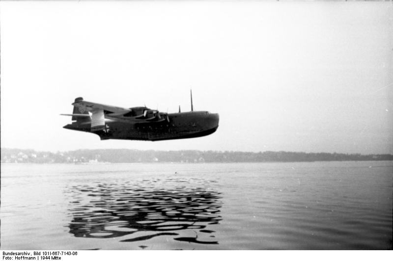
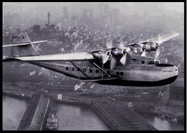
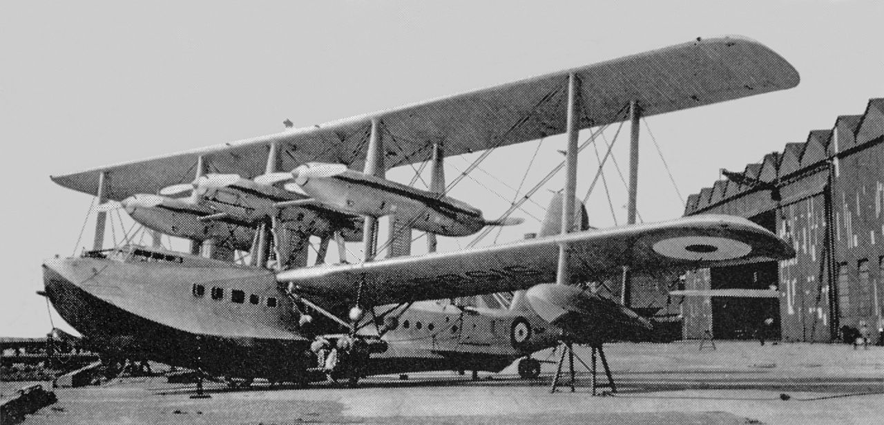
Consolidated was a well established manufacturer of long range flying boats for the American Navy, such as the PBY-Catalina and PB2Y-Coronado. The engineering department under Isaac ‘Mac’ Laddon was working at that time on a successor for the Catalina, which would be called (until the intended procurement by the Navy), the Model 31 Corregidor. There were also negotiations going on regarding production licenses for the Boeing B-17, the heavy four-engined Army Air Corps bomber.

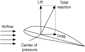
Enter Davis, introduced by Brookins to the top of the firm as a technical wizard with special interest in long range flight. For the last several years he had been working on wing design, with special attention to the cross sectional shapes of wings. He claimed to have developed better wings than NACA, the official federal aviation research authority. To prove it he presented his hosts with his Patent 1,942,688  “FLUID FOIL” of Jan.9.1934.

The Consolidated executives received their guests politely and, after the introduction, proceeded to look somewhat bewildered at the presented patent. It showed numerous unwieldy pairs of formulas apparently describing the form of the upper surface of a wing section (suction side) and of the under surface of the same wing section (pressure side). It should be noted that the formulas contained multiple appearances of two parameters, A and B, whose actual values were left unspecified. Written in this way, the paired formulas did not describe a single wing section, but a whole family of sections.

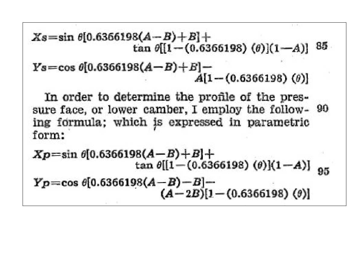
On page 2 of the patent a single example of calculation was given, where A had received the value: A=0.717257 and B=0.208228. When these values were substituted in the formulas a smooth looking wing shape resulted as shown in Fig.1 on page 0 of the patent and reproduced here at the top of this article.

Page 3 of the patent (see picture below) left the technical staff of Consolidated even more bewildered.
Laddon:    Where on earth did you find these formulae?
Davis:         I derived them from theory.
Laddon:    Theory? Aerodynamic?
Davis:         Yes, hydrodynamic, the Magnus force on a rotor moving in an air stream.  But the derivation is not part of the patent.
Laddon:     I see.

Page 3 of Davis’patent is full of repeated pairs of identical formulae and leaves the casual reader bewildered

They then had a long discussion about the required values for the A and B parameters. The Davis’ patent stated that A influenced the lift force delivered by the wing at a certain angle of attack and B the fluid resistance (drag). Consolidated required, for long range cruise flight, as low an air drag as possible at a relatively high angle of attack. What values of A and B would be best?
Davis promised to disclose the desired parameters if Consolidated agreed to use his wing section for actual production aircraft and pay him a certain royalty per airplane sold.

I am not informed how much time these discussions took, but the evidence is there that the negotiations were intense. Davis must have mentioned that he could show certain results from model experiments. However, I am not sure he told the other party how he had been able to obtain these test results.

As Vincenti recounts:

To settle the uncertainties, the two parties decided to send one model of a Davis airfoil in addition to a standard NACA model of Consolidated’s choice to the so-called ’10 foot wind tunnel’ of the Guggenheim Aeronautical Lab at Caltech in Pasadena to let an unbiased party make the comparison. Both wind tunnel models were for a wing of the same planform en depth. Davis personally fabricated his sample to a high degree of surface perfection (with shape parameters A=1 and B=-1). The Consolidated entry followed the standard specs for a NACA 21-series wing section.

1930: Prof Clark Milligan at the unfinished Galcit windtunnel

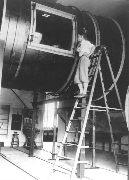
The test results confounded GALCIT professor Clark Milligan to a high degree. The Davis section showed very low friction even at high angles of attack. Even after re-finishing Consolidated’s NACA model to the same surface specs, the Davis section turned out to be superior. A total of three trials gave near identical results.

David Davis working on the layout of his wing section (source: Vincenti)

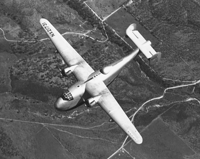
Everybody finally agreed that the Davis design was not a bad choice at all. The engineers caught the spirit of things and said: why not use it for the wing of the Corrigedor that we are building now? So they did and although the big boat looked according to some like a ‘pregnant guppy’  it flew like a lark (see my previous blog on this subject). 

1933: Prof. Clark Milligan plus assistent at work inside Galcit tunnel on Douglas DC-3model

Meanwhile, Major Fleet communicated with his network at the Air Corps and he got the approval to build a prototype heavy bomber with the new wing. The wing was amazingly slender and prolonged long distance flying by some 10% and saved fuel on regular runs to an equal amount.

The prototype was designed and built in nine months and flew one day before the contract stipulated, on December 29, 1939.

B-24 Liberator: Crew before first test flight December 29 1939.

The B-24 Liberator and its many variants turned out to be a big success for Consolidated Aircraft and for David R. Davis. According to Wiki a total of 18,500 were constructed. Their war record in Europe and in the Pacific theater was most impressive.

David Davis received his royalties, but his name was never mentioned, not by Galcit, not by academia in general, except for Dr. Vincenti,  who wrote the very well researched definitive account on which this blog is based.
NACA did not waste time in developing its own competing wing profile that was used in the North American P-51 long distance fighter.

Sources of Illustrations:
in text:
http://sandiegoairandspace.org/exhibits/online-exhibit-page/consolidated-convair-online-exhibit
https://www.nationalaviation.org/our-enshrinees/fleet-reuben/
Galcit:
http://windtunnel.caltech.edu/tenfoot/index.htm

2000: MY PRIVATE HISTORY OF THE DAVIS-WING III

I must now finish my private history of the Davis wing before my memory gives out completely.

Tantalizing about this wing was the fact that before the year 2000 so little was published about its remarkable airfoil (wing cross section) in the official annals of American aviation history.  How was its form discovered? Who was Mr. Davis? What was so special about it?

In the Creed book of 1985 about the Consolidated Catalina [1] that I refer to elsewhere on my site, the wing was briefly mentioned in one paragraph as being used on a special 1939 Consolidated flying boat (the Model 31 Corrigedor) and on the upcoming B-24 Liberator bomber. But how did this revolutionary design pop up in the practice of airplane design of that period? Why was everybody, including NACA, so silent about it? Why was there no readily available publication? Why did Mr. Davis not get offered a professorship at Caltech?

1939: Consolidated Model 31 Corrigedor with Davis wing   [also shown at top of page]

At that time (around the year 2000) the computer center of the Public Library in Arnhem (The Netherlands), where I spent many of my spare hours, started to provide service with a new program called Google, with which the uninitiated could search the Wide World Web to his or hers heart’s content. So, deciding a wild try on my own, I typed in “Davis wing design” and to my surprise I received 0,314 seconds later a list of suggested reading, with on top the title of a  book:

“Walter C. Vincenti: “What Engineers Know and How They Know It”. 
Analytical Studies from Aeronautical History – John Hopkins Studies in the History of Technology. – The John Hopkins University Press (1990, 325 p.)
And lo and behold, when I looked more closely, the book contained a second chapter with the title: 
“Design and the Growth of Knowledge: The Davis Wing and the Problem of Airfoil Design

To me this was astounding: Google had not just found a character-by-character match with my search argument, but had found this match within a book with a non-corresponding title! From that day on my admiration for Google (and its many amazing products) has only increased.


A short time later I managed to obtain the very book, second hand, via the Crawford & Peters book store in San Diego that my Canadian friend John Gallipeau had located for me and within weeks I was reading chapter 2, page 22 to 33. 

The author, Walter Vincenti, is an aeronautical engineer but talks the philosopher’s lingo, using words like ‘epistemology’ and ‘presumptive anomaly’.  I for me would have liked a more straight account and maybe some  attention to the creativity and the personal flair of the engineers-in-charge at the early stages of the design process, but the story of how the Davis wing came to be used in the Second World War with 18,450(!) B-24 Liberator bombers and transport planes is all there.

B-24 Liberator – note its slender Davis wing

In one of my earlier blogs on this subject I have assumed that the Davis wing would  have been thin in order to be suitable for high speeds. I now read in Vincenti: “….‘to reduce drag, the pressure in the airflow on top of the wing should decrease as gradually as possible and should reach a minimum as far to the back of the wing as possible.’
This meant that Davis was in fact constructing an airfoil with a very slowly changing curvature at the leading edge, resulting in a profile with a very thick center: a so-called laminar flow profile. In his patent he gave a formula for the exact shape of the section, based on the shape of a cycloid, that is the path that a point on your tire tread describes in space as your car travels down the road. Davis would not explain how he derived the formula, indeed certain coefficients were in doubt until the very end.

Dr. Vincenti explains that David Davis had been searching for a wing design which presented relative low air friction (drag) at high cruising speed. At cruising speed the engines would be kept at a low power setting in order to save on gas consumption. The total drag of the airplane needed therefore to be low. This meant that the wing, while delivering sufficient lift, should present minimum drag.

The drag of a wing in flight has two parts: the induced drag that is generated by the lifting action of the wing as it moves through the air and the profile drag which is the resistance force that is felt by any frontal surface that is facing an air stream. I had thought previously that the wing had to be thin in order to have a low profile drag, but Davis reasoned differently. He argued that a teardrop shape gives mimimal profile drag: a shape with a relatively blunt nose, a curvature getting thickest toward the middle of the wing and then relatively straight flanks toward the pointed trailing edge. It resembles in fact the elongated tear drop shape of a zeppelin.

In addition, a wing cross-section shaped like this has an important advantage to the structural designer: it can accommodate two hefty front and rear wing spars that are needed to carry a wing with a large span. The larger the span, the lower the induced drag will be, but the higher the bending moments at the root of the wing , so the wing will need a strong internal supporting structure.
A deep wing would provide a nice roomy central space between the spars to house the fuel tanks and the retracted wheels of the airplane.

TO BE CONTINUED  


[1] Roscoe Creed in “PBY The Catalina Flying Boat”; Naval Institute Press, Annapolis, 1985 

THE BIRTH OF THE ATLANTIC AIRLINER

C69LHCONNIEg

Well, today I finally finished the last part of my reflections on the history of the “Atlantic Airliners”, that is, the story how designers and other craftsmen learned to make metal birds that carry passengers safely across the great ocean.

So quick, go to the top edge of this page and click on Early Atlantic Airliners and download the pdf files for free!
(By the way, visit also the beautiful website where I found the above picture:
https://www.scribd.com/doc/280054952/Lockheed-Constellation-From-Excalibur-to-Starliner )

Now the last blog I have to write is to finish this Davis wing story. It’s coming – give me a bit of time.  Lemesee, what was it about again??

1994: MY PRIVATE HISTORY OF THE DAVIS-WING II

In 1994  I bought a handsome collection of short biographies of aviation pioneers, from which I quote:

The Wing Man: David R. Davis – 1894(?) – 1972  [1]
“David Davis grew up as a sickly child who was advised to spend as much time outdoors as possible. While a young man, he was sent on an educational camping trip with a tutor, during which they retraced the route of Lewis and Clark. [2]   When he was fifteen he moved to California with his mother. Their home was near Los Angeles where [aviation pioneer] Glenn Martin was experimenting and Davis would often help Martin ground-handle his plane.

“In 1911 Davis made his first flight and four years later he bought his first aeroplane. During World War I he served in the Army.  After the war he became a barnstormer before joining with Donald Douglas in 1920 to start the Davis-Douglas Airplane Company  [Davis put up $40,000.] This venture failed and Davis was completely wiped out with the Stock Market crash in 1929.”

About the period with Douglas, Oliver E. Allen writes in “The Airline Builders:[3]

“…In 1920 Douglas was ready to start his own firm. He went to Southern California with less than $1000 because he felt at home there and one could fly there all year. It was however a bad time to start an aircraft factory anywhere. Douglas tried to borrow money everywhere, until a friend introduced him to David R. Davis, a well to do young man from California who wanted to have an airplane built for a non-stop transcontinental flight.”

04-02366-donald-w-douglas-and-david-r-davis-formed-davis-dou
Donald W.Douglas (left) and David R. Davis [0]
“The two men founded the Davis-Douglas Co. and rented an office. Afterwards they moved to a loft over a lumberyard in Los Angeles. There they constructed the Cloudster. This airplane had one unique property: it was the first plane that could transport a load greater than its own weight.  During the first [attempt of] transcontinental flight the [Liberty] engine broke down and Davis had to crash land at Fort Bliss (Texas). In 1923, when he was ready for a second attempt, two army officers had already completed the non-stop flight with a Fokker T2.  Davis lost interest and withdrew from the company…”

Quoting again from Longyard:
“…Davis took an everyday job to support his family but he never gave up his penchant for airplanes. He tried to develop a variable pitch propeller, but lack of funds hampered his efforts. By the late 1930s, he had developed a theory of aerofoils that he thought could greatly increase the efficiency of wings. He tested model sections mounted on a borrowed car.

Reuben Fleet, founder of Consolidated Aircraft

Through Walter Brookins, he was able to convince Reuben Fleet  [4]
owner of Consolidated Aircraft, of the possibilities inherent in his new wing. Fleet had a wing section tested at the California Institute of Technology where the scientists said the wing was an impossible 102 percent efficient. They disassembled their windtunnel to see what was wrong! Fleet ordered that his next flying boat be built with a ‘Davis Wing’ – a million dollar gamble. In 1939 this plane [the  Model 31 Corregidor] was flown by an amazed test pilot who said it handled like a fighter.”

Altogether not a very complete picture of what exactly went on with the Davis-wing. Remember this was the time before Google, Internet and Wiki. In those days one had to search in libraries and magazines. So imagine what a surprise it was when one day in 1996 I found a letter in the mail from my old friend of Canadian days John Gallipeau, whom I had not seen for thirty years. He had heard of my interest in the Davis wing and he had visited the San Diego Air & Space Museum, where he had found fresh information for me, such as the photograph of two of the principal actors shown above: Donald Douglas and David R. Davis.

Notes
———————–
[0] Picture of Cloudster is shown at the top of the article. Note the big belly needed to store all the fuel.    (Pic credit: Wiki)
[1] The collection of short biographies is from: William H. Longyard, “Who’s Who in Aviation History“, Shrewsbury, Airlife, 1994.
[2]  Two famous explorers, who were sent out by Thomas Jefferson in 1803 to find a route from St.Louis to the Pacific Coast.
[3] Chicago, Time/Life, 1981, here translated from the Dutch edition.

[4] Two more actors had appeared on the scene. Who was Brookins?according to: http://www.oac.cdlib.org/findaid/ark:/13030/kt0489r3ch/):
Walter Richard Brookins was born in Dayton, Ohio, on July 11, 1888. He first knew Orville and Wilbur Wright at the age of four, and was a student of their sister, Katherine, a school teacher. As a teenager he spent much time at the Wright brothers’ bicycle shop, observing them testing their theories, and after their successful first flight the brothers promised Brookins a plane as soon as he was old enough.
Brookins was the first civilian pilot taught to fly by Orville Wright, taking to the air after two and a half hours of instruction, controlling a flight from start to finish on April 30, and flying alone for 12 minutes on May 6.
On July 10, 1910, at Atlantic City, he became the first person to reach an altitude of one mile in an airplane, winning a $5,000 prize for the Wright Company from the Atlantic City Aero Club, and on September 29, 1911, he set an American distance record by flying 192 miles from Chicago to Springfield, IL, making two stops.
Acording to Longyard:
“… During the pre-WW1 years he [Brookins] earned a national reputation as a daring stunt pilot… [He]made the first nightflight in America [1910]… He later established the Brookins Aircraft Coporation in Los Angeles. He unwittingly dramatically affected the course of bombing history when he introduced David Davis to Reuben Fleet, so that Davis might sell Consolidated Aircraft his special wing design.”

Reuben Fleet of course was the legendary founder and owner of the Consolidated Aircraft Corporation. (see also: page 7,  https://ritstaalman.files.wordpress.com/2014/09/laddon-catalina2.pdf)
Originating from Buffalo NY, the firm was moved to San Diego, near the naval base, when Fleet acquired orders for a large number of flying boats for the US Navy.

Much detail about the initial years of Consolidated is given by: Roscoe Creed in: “PBY, The Catalina Flying Boat” (Annapolis, Naval Institute Press, 1986). Creed also describes the Davis-wing trial with the successor to the famous PBY Catalina, which was developed as a private project by Consolidated, under the name Model 31, later Corregidor.

to be continued…

1985: MY PRIVATE HISTORY OF THE DAVIS-WING

I got interested (again) in aviation history when I bought thirty years ago at a jumble sale an old scrap book with photographs of the Dornier Do-X. The picture shown above carried the caption (in Dutch):

1929
THE BIGGEST AIRPLANE IN THE WORLD, the Do X, has recently been completed in the halls of Dornier in Friedrichshafen and will make soon its first test flight. This immense aeroplane has a length of almost forty meters; the span of its wings comes to 48 meters and its height is 8.5 meters. The giant will be propelled by no less than 12 large Siemens Jupiter engines with a total power of 6200 hp. The fuel tanks are in the bottom of the airplane reducing the danger of fire almost completely. The number of passengers that can be transported is astounding: no less than 100!
There is a crew of twenty needed to control the airplane and serve the passengers. The creator of this enormous colossus, Ir. Dornier, has stated that three or four of the engines may be stopped during flight without problems. However, the crossing of the ocean is not yet possible with this giant – it is not more than a step forward on the difficult road to trans-oceanic air traffic. On the photograph the immense monoplane is shown in the assembly hall of the Dornier factory.

The Germans have always been very proud of their Do-X – and rightly so – but of course in 1932, as predicted, it failed where five years earlier Charles Lindbergh had succeeded without apparent effort:
a simple non-stop jump across the Atlantic.


I wondered why this would be so and started to read (+ collect) books about 1930-flying boats and airliners. What were the factors that determined their long-range performance? How fascinating that era was!

Next I got into a correspondence with a certain Don Middleton, a British aviation journalist, who had stated in an English monthly that the amazing long range of the Consolidated Catalina patrol boat was due to its ‘Davis-wing’. Based on general data from Jane’s ‘Fighting Aircraft of WWII’ edition I undertook to compare four contemporary transport planes: the Douglas DC-3 and DC-4, and the Consolidated Catalina and B-24 Liberator, and proved to him that Catalina’s extreme performance was based on two factors: its light construction (empty weight approximately 50% of take-off weight) and its slow cruising speed, which was right at the optimal economic flight point (maximum  CL/CD ratio). The other three planes, for commercial or operational reasons, all cruised faster than their most economic speed and as a consequence had a comparatively shorter range. The Cats were slow, real slow, to the exasperation of their crews. However, slowness could also be advantageous: they were able to shield the ships they were escorting by circling tightly around them, outmaneuvering in this way attacking German and Japanese aircraft that were much faster.

Consolidated PBY Catalina

The PBY Catalina had no Davis-wing and I think I proved it, but Middleton never entered into a serious discussion and suggested I submit my paper to the Royal Aeronautical Society, which of course was a bit much. Later on I learned he disliked smart asses like me who argued from theory: he had been a skilled aircraft worker at de Havillands himself and a RAF engineer during the war.
Of course the Davis-wing was used on the B-24 Liberator. Next blogs will summarize what I know about it. The inventor, David R. Davis, [1] appeals to me because he was obviously a maverick: he worked outside the official circuits of Universities and NACA. Apparently he had a mind of his own.
As a result however, descriptions of his work are hard to find in official literature (like Abbott & Doenhoff; maybe Durand mentions him?). Apparently his wing had extreme low drag at small angles of attack (laminar flow?), which is remarkable, because long range (like Catalina’s) is usually associated with low engine power and therefore relative large angles of attack. So there were things here which were not quite clear to me. I wanted to know more about the wing profile: it must have been very thin with maximum depth near the middle of the chord. How can thin wings be made strong enough for long spans? This was the state of my comprehension (and confusion) until I found more information.

[1] A word of warning: there have been other aviators of fame with the name Davis. So is our man not to be confused with the unfortunate pilot Noel Guy Davis, who crashed short after take-off for a trans-Atlantic flight in 1927, aboard a Keystone Pathfinder (N-X179) airplane called American Legion.
[2] picture: PBY5 Catalina; credit: Wiki.

2015; spring – WORK IN PROGRESS

McDonnell_Douglas_Long_Beach YC-15The McDonnell Douglas YC-15 under construction at Long Beach CA
(this was some time ago).

Also some time ago:
Sikorsky S-38 at OshkoshPhotographed at Oshkosh: the Sikorsky S-38

castawayMarch23 f

I wonder if she can land at Newport Beach and pick us up.
We’ll climb aboard and  fly with her for ever west into the setting sun

Meanwhile we are working on an update of the Willy Fiedler story
(see: From Fledermaus to Polaris). Anybody who has memories of Willy or documents about his work is invited to contact us.

2015: ATERRISSAGE – HAPPY LANDING

Hold fast to dreams For if dreams die Life is a broken-winged bird That cannot fly. Hold fast to dreams For when dreams go Life is a barren field Frozen with snow. Langston Hughes
Huntington Beach,  California

The Ocean,

the beginning and the end.

479px-Maxwell_B-24
Consolidated B-24 Liberator

I wonder who will be coming to pick us up.

This big boy from San Diego?

It has a wonderful wing.  Its hull is from a flying boat.

It can’t land here. Just casing the place, I suppose.

Flugzeug Blohm & Voß BV 238 V1
Blohm & Voss BV-238 (100 tons)

The biggest one built in Germany, in Bremen, during the war.  It might be able to land here.

Rumor had it that Der Führer was planning to escape with it to Argentina.

I bet its designer, Dr. Vogt, never thought he would end up close by here, in Santa Barbara.

Martin M130
Glenn-Martin M-130 Clipper

The best one ever built.
It conquered  the Pacific

Latecoere 521 Flying Boat12A

As Boeing knows: never underestimate the French

H-4_Hercules_2
Hughes / Kaiser HK-1 Spruce Goose

This one is retired now in Oregon.

Pity it never really flew.

400px-Australian_pelican_in_flight

This one still flies.

May it outlive us all.

Au Revoir!

Ω

1934: A PLANE IS NOT A SHIP

Revolutionary Sikorsky S-42 (1934)

Sikorsky’s factory in Stratford Connecticut completed its first S-42 airliner/flying boat in March 1934 and Igor Sikorsky took at the earliest opportunity the mail boat to Southampton to promote his revolutionary clean looking flying machine in the Old World. His first stop was London where he delivered a glowing lecture with epidiascope projections to the Royal Aeronautical Society. His new ship was fast and it could move passengers far. In fact in the years that followed, Pan American Airways bought ten of them and used them to conquer the Pacific Ocean. The British aviation bigwigs and tech wizards listened in polite astonishment. Igor gave a glowing account of his breakthrough in the design dilemmas that had for thirty years produced only ugly-looking mechanical flying things with a multitude of wings, struts and wires.

Ugly Short S-14 Sarafand (1932)

Sikorsky had now created a roomy airplane with a single sleek small wing and four beautifully mounted engines. It carried 12 passengers with ease over 2000 miles and it could alight gently at 65 mph on the tops of the rolling waves. Its cruising speed was 160 miles per hour and Igor repeatedly pointed out how this speed in combination with the high wing load made for a comfortable ride, relatively insensitive to wind gusts and sudden vertical up and down air drafts.

IGOR I. SIKORSKY (1889-1972)IGOR I. SIKORSKY    (1889-1972)

The British listened with polite amazement and suppressed skepticism. “We don’t really need speed”, said Mr. Horace Short, the builder of England’s famous double-breasted multi-wing lumbering patrol boats during the discussion afterwards.”When we need speed we’ll have Supermarine win the Schneider Cup or Messrs. de Havilland will build the Comet for winning the Melbourne race. We focus on other things.” He meant safety, a slow landing speed. And it must be said, his boats had an enviable safety record (but could not cross the ocean).
Mr. M.Langley inquired whether Mr. Sikorsky had used Imperial or US Gallons in his specifications. He apparently couldn’t believe the figures and the British ones were a good deal larger.
As to performance, Mr. W.O. Manning conceded frankly that Mr. Sikorsky had put the flying boats used by Imperial Airways completely out of date. He then proceeded to produce a global new design on the lines of the S-42 and showed its superiority.
Major R.E. Penney thought the secret of Mr. S.’s boat could be found in the enormous amount of detail work, the fairing up of the details so that the combined resistances had been reduced to an absolute minimum.

Phoebastria_albatrus (picture: Wiki)

Mr. Scott-Hall mentioned in passing that albatrosses (the birds) had a large wing load but they had trouble getting themselves up in the air. And so there was a lot of back and forth talk about speed and small wings.
Until finally Major F. Green hit on the real issue: “Let’s not overlook the fact that a small wing saves a substantial amount of weight”. And here was of course the quintessence: instead of carrying wing, the airplane could now carry fuel and people. But even Igor did not seem to quite grasp the point. He came back to the subject of speed. “There is no doubt”, he stated, “that planes of great weight, capable of non-stop ocean flights, cruising between 150 to 200 miles per hour, can be designed at this time and be ready for service within two and a half to three years. Greater cruising speeds are possible, but the size of the earth does not warrant greater speeds. The progress of air transportation will benefit more if designers will give more attention to increased passenger comfort and ways and means to lower transportation costs rather than greater speed.”
Well now, would that really be possible Mr. Sikorsky? Are speed and economics independent quantities?
A cat is not a dog and a plane is not a ship.

for the full text of Igor Sikorsky’s lecture, click:  https://ritstaalman.files.wordpress.com/2014/12/sikorskya.pdf
see also Part III of Early Atlantic Airliners:  ATLAIRpart3
for books on the conquest of the Atlantic by air: http://www.Lindbergh-aviation.de atta12e9

1933: High Fashion in Wings

We exchanged some polite remarks while we heaved our bags in the rack above us and sought our proper place. We just fitted in our seats together: the blonde lady in sweater and jeans at the window, I in the middle and to my right the middle aged guy in safari jacket with long hair in a ponytail… Then we underwent in silence the start of the machine and the handout of some gorgeous delicacies like peanuts wrapped in tiny little plastic bags.

picture by Monica Staalman

After a while the plane had climbed to cruising height and I bent forward to the left to look out of the window. I saw an elegant upward turned wing tip against the hard blue expansion of the universe and the faintly curved horizon of our planet.
“Isn’t it amazing?”  the lady smiled at me – “how we are sitting here crunching peanuts above the world?”
“It’s stunning,” I agreed. – “I was also observing the wing tip. There seems to be a fashion nowadays to bend them upward.”
“Well dear, it’s all about saving fuel you know. The proper shape may give you an extra 3 or 4 per cent range. It all counts with the present fuel prices.” (This conversation took place some years ago).
“How can that be?”
She explained: “The wings leave behind a corkscrew of whirling air, one at each side. It is an air vortex. In a way you may say that the airplane pulls the vortex forward. The bigger the vortex, the more energy it takes from the plane. With careful design of the wing tip the engineers try to make the generation of the vortex more gradual, less violent, see?” She looked at me and smiled.

this magnificent picture is from NASA, via Wiki. See note below

“Yeah,” the man to my right added -“and these vortices are bloody dangerous for the little guy who is flying behind them. You better stay out of the wake of the big ones…”
And so it turned out to be a pleasant flight for all of us. The safari chap ordered a meal and offered me his dessert because he was, as he explained, a diabetic. The lady at the window knew more about airplanes than any of us. And I told them about Willy Fiedler who had built and flown a sailplane in 1933 with vertical wing tips and no fin at the tail. I even showed them a picture on my i-phone.
They were properly impressed.

We spent the rest of the flight with pleasurable chitchat. However, as always when flying, I lost my new friends at the Luggage Claim.  If we had traveled by steamship we would probably still be in contact now.

1933: Aka Flug Stuttgart F-1 Fledermaus, design Willy Fiedler

1933: Aka Flug Stuttgart F-1 Fledermaus, design Willy Fiedler

See also:

https://earlyflightera.com/from-fledermaus-to-polaris/

http://en.wikipedia.org/wiki/Wingtip_device

http://en.wikipedia.org/wiki/Wake_turbulence where you will find:

DescriptionAirplane vortex edit.jpg (see earlier picture)
Date  4 May 1990
English: Wake Vortex Study at Wallops Island
The air flow from the wing of this agricultural plane is made visible by a technique that uses colored smoke rising from the ground. The swirl at the wingtip traces the aircraft’s wake vortex, which exerts a powerful influence on the flow field behind the plane. Because of wake vortex, the Federal Aviation Administration (FAA) requires aircraft to maintain set distances behind each other when they land. A joint NASA-FAA program aimed at boosting airport capacity, however, is aimed at determining conditions under which planes may fly closer together. NASA researchers are studying wake vortex with a variety of tools, from supercomputers, to wind tunnels, to actual flight tests in research aircraft. Their goal is to fully understand the phenomenon, then use that knowledge to create an automated system that could predict changing wake vortex conditions at airports. Pilots already know, for example, that they have to worry less about wake vortex in rough weather because windy conditions cause them to dissipate more rapidly.

1930’s: LIGHT METAL WINGS I

main spar box Boeing
picture source: navyaviation.tpub.com

“…The ability of sheet metal to carry an increasing load after it had begun to buckle – which in conventional structures was regarded as failure – was crucial to the development of metal airplanes. It had first been discovered in 1925 by Dr.Herbert Wagner, who was then working for the Rohrbach Metall-Flugzeugbau in Berlin, Germany, but his findings were not published until 1928 in English by NACA. Northrop’s work was done independantly. Wagner went further than Northrop in his analysis of the way in which a thin sheet of metal behaves when supported at the edges, as it is in airplane structures, and he evolved the theory of the diagonal-tension field beam to explain it. This theory, and elaborations of it, formed the basis for the development of a/c structures from the mid 1930’s onward. But it was not applied to the early Northrop airplanes or the Douglas DC-1-2-3. Northrop’s construction gave a good enough ratio of strength to weight for these airplanes, and the use of Wagner’s theory would have added to the complication and cost of design…”

The above quotation is from: Ronald E.Miller; David Sawers, “The Technical Development of Modern Aviation” (Routledge & Kegan Paul: London; 1968) p.65
In August 1933 Paul Kuhn  wrote an explanation of Wagner’s theory as NACA Technical Note No. 469 “A Summary of Design Formulas for Beams Having Thin Webs in Diagonal Tension”,  Langley Memorial Aernautical Laboratory. Washington,. A copy of this paper may be downloaded from the Herbert Wagner page on this website.