
I must now finish my private history of the Davis wing before my memory gives out completely.
Tantalizing about this wing was the fact that before the year 2000 so little was published about its remarkable airfoil (wing cross section) in the official annals of American aviation history. How was its form discovered? Who was Mr. Davis? What was so special about it?
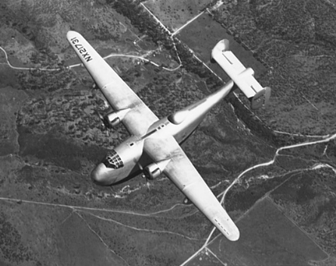
In the Creed book of 1985 about the Consolidated Catalina [1] that I refer to elsewhere on my site, the wing was briefly mentioned in one paragraph as being used on a special 1939 Consolidated flying boat (the Model 31 Corrigedor) and on the upcoming B-24 Liberator bomber. But how did this revolutionary design pop up in the practice of airplane design of that period? Why was everybody, including NACA, so silent about it? Why was there no readily available publication? Why did Mr. Davis not get offered a professorship at Caltech?
At that time (around the year 2000) the computer center of the Public Library in Arnhem (The Netherlands), where I spent many of my spare hours, started to provide service with a new program called Google, with which the uninitiated could search the Wide World Web to his or hers heart’s content. So, deciding a wild try on my own, I typed in “Davis wing design” and to my surprise I received 0,314 seconds later a list of suggested reading, with on top the title of a book:
“Walter C. Vincenti: “What Engineers Know and How They Know It”.
Analytical Studies from Aeronautical History – John Hopkins Studies in the History of Technology. – The John Hopkins University Press (1990, 325 p.)
And lo and behold, when I looked more closely, the book contained a second chapter with the title:
“Design and the Growth of Knowledge: The Davis Wing and the Problem of Airfoil Design”
To me this was astounding: Google had not just found a character-by-character match with my search argument, but had found this match within a book with a non-corresponding title! From that day on my admiration for Google (and its many amazing products) has only increased.

A short time later I managed to obtain the very book, second hand, via the Crawford & Peters book store in San Diego that my Canadian friend John Gallipeau had located for me and within weeks I was reading chapter 2, page 22 to 33.
The author, Walter Vincenti, is an aeronautical engineer but talks the philosopher’s lingo, using words like ‘epistemology’ and ‘presumptive anomaly’. I for me would have liked a more straight account and maybe some attention to the creativity and the personal flair of the engineers-in-charge at the early stages of the design process, but the story of how the Davis wing came to be used in the Second World War with 18,450(!) B-24 Liberator bombers and transport planes is all there.

In one of my earlier blogs on this subject I have assumed that the Davis wing would have been thin in order to be suitable for high speeds. I now read in Vincenti: “….‘to reduce drag, the pressure in the airflow on top of the wing should decrease as gradually as possible and should reach a minimum as far to the back of the wing as possible.’
This meant that Davis was in fact constructing an airfoil with a very slowly changing curvature at the leading edge, resulting in a profile with a very thick center: a so-called laminar flow profile. In his patent he gave a formula for the exact shape of the section, based on the shape of a cycloid, that is the path that a point on your tire tread describes in space as your car travels down the road. Davis would not explain how he derived the formula, indeed certain coefficients were in doubt until the very end.
Dr. Vincenti explains that David Davis had been searching for a wing design which presented relative low air friction (drag) at high cruising speed. At cruising speed the engines would be kept at a low power setting in order to save on gas consumption. The total drag of the airplane needed therefore to be low. This meant that the wing, while delivering sufficient lift, should present minimum drag.
The drag of a wing in flight has two parts: the induced drag that is generated by the lifting action of the wing as it moves through the air and the profile drag which is the resistance force that is felt by any frontal surface that is facing an air stream. I had thought previously that the wing had to be thin in order to have a low profile drag, but Davis reasoned differently. He argued that a teardrop shape gives mimimal profile drag: a shape with a relatively blunt nose, a curvature getting thickest toward the middle of the wing and then relatively straight flanks toward the pointed trailing edge. It resembles in fact the elongated tear drop shape of a zeppelin.

In addition, a wing cross-section shaped like this has an important advantage to the structural designer: it can accommodate two hefty front and rear wing spars that are needed to carry a wing with a large span. The larger the span, the lower the induced drag will be, but the higher the bending moments at the root of the wing , so the wing will need a strong internal supporting structure.
A deep wing would provide a nice roomy central space between the spars to house the fuel tanks and the retracted wheels of the airplane.
TO BE CONTINUED
[1] Roscoe Creed in “PBY The Catalina Flying Boat”; Naval Institute Press, Annapolis, 1985
