We exchanged some polite remarks while we heaved our bags in the rack above us and sought our proper place. We just fitted in our seats together: the blonde lady in sweater and jeans at the window, I in the middle and to my right the middle aged guy in safari jacket with long hair in a ponytail… Then we underwent in silence the start of the machine and the handout of some gorgeous delicacies like peanuts wrapped in tiny little plastic bags.

After a while the plane had climbed to cruising height and I bent forward to the left to look out of the window. I saw an elegant upward turned wing tip against the hard blue expansion of the universe and the faintly curved horizon of our planet.
“Isn’t it amazing?” the lady smiled at me – “how we are sitting here crunching peanuts above the world?”
“It’s stunning,” I agreed. – “I was also observing the wing tip. There seems to be a fashion nowadays to bend them upward.”
“Well dear, it’s all about saving fuel you know. The proper shape may give you an extra 3 or 4 per cent range. It all counts with the present fuel prices.” (This conversation took place some years ago).
“How can that be?”
She explained: “The wings leave behind a corkscrew of whirling air, one at each side. It is an air vortex. In a way you may say that the airplane pulls the vortex forward. The bigger the vortex, the more energy it takes from the plane. With careful design of the wing tip the engineers try to make the generation of the vortex more gradual, less violent, see?” She looked at me and smiled.
“Yeah,” the man to my right added -“and these vortices are bloody dangerous for the little guy who is flying behind them. You better stay out of the wake of the big ones…”
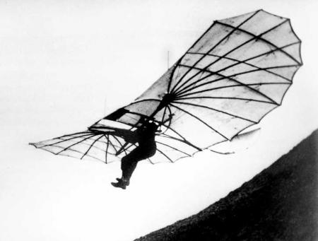
And so it turned out to be a pleasant flight for all of us. The safari chap ordered a meal and offered me his dessert because he was, as he explained, a diabetic. The lady at the window knew more about airplanes than any of us. And I told them about Willy Fiedler who had built and flown a sailplane in 1933 with vertical wing tips and no fin at the tail. I even showed them a picture on my i-phone.
They were properly impressed.
We spent the rest of the flight with pleasurable chitchat. However, as always when flying, I lost my new friends at the Luggage Claim. If we had traveled by steamship we would probably still be in contact now.
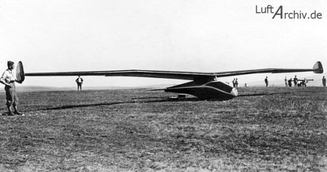
1933: Aka Flug Stuttgart F-1 Fledermaus, design Willy Fiedler
See also:
https://earlyflightera.com/from-fledermaus-to-polaris/
http://en.wikipedia.org/wiki/Wingtip_device
http://en.wikipedia.org/wiki/Wake_turbulence where you will find:
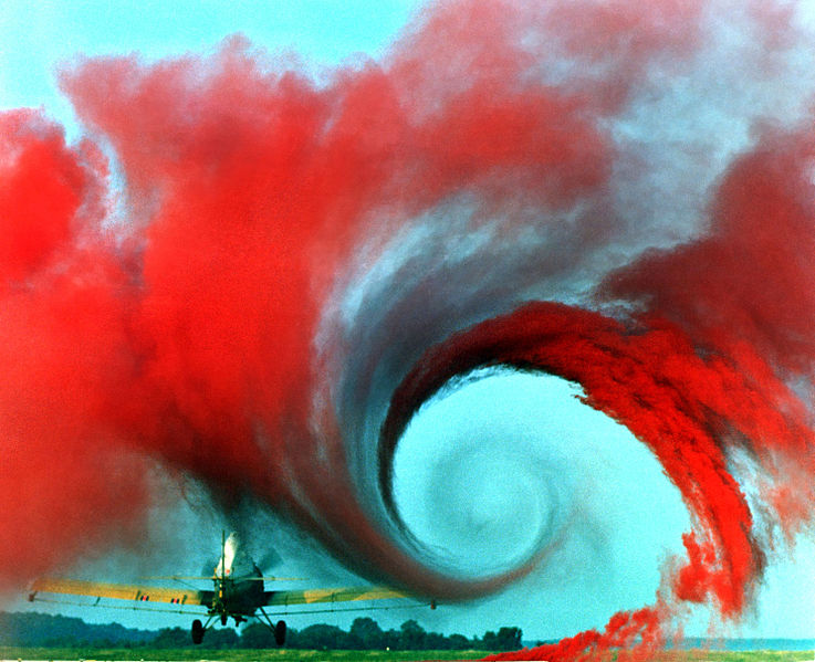
DescriptionAirplane vortex edit.jpg (see earlier picture)
Date 4 May 1990
English: Wake Vortex Study at Wallops Island
The air flow from the wing of this agricultural plane is made visible by a technique that uses colored smoke rising from the ground. The swirl at the wingtip traces the aircraft’s wake vortex, which exerts a powerful influence on the flow field behind the plane. Because of wake vortex, the Federal Aviation Administration (FAA) requires aircraft to maintain set distances behind each other when they land. A joint NASA-FAA program aimed at boosting airport capacity, however, is aimed at determining conditions under which planes may fly closer together. NASA researchers are studying wake vortex with a variety of tools, from supercomputers, to wind tunnels, to actual flight tests in research aircraft. Their goal is to fully understand the phenomenon, then use that knowledge to create an automated system that could predict changing wake vortex conditions at airports. Pilots already know, for example, that they have to worry less about wake vortex in rough weather because windy conditions cause them to dissipate more rapidly.

![Northrop wing with skin removed showing longitudinal stringers [from: WoodToMetal.pdf SI 94-7718]](https://earlyflightera.com/wp-content/uploads/2014/12/northropwing1.jpg)