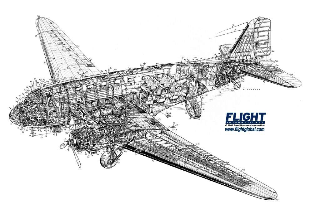
When, in 1953, in my capacity of apprentice in the KLM Maintenance Service at Schiphol, I started one morning to help take off half the wing of a Douglas DC-3, I was most astonished to find that the wing of this rather famous and historic airliner had no sturdy spar in its innards, but that the metal wing cover had a seam from front to back at a position close to the engine, where it was simply bolted to the center section of the airplane.
Only recently I read that this particular construction was called ‘multi-spar’ and invented by Jack Northrop around 1930. In document 3-22(a-b) 3-22-b: Engineering Department, Douglas Aircraft Co. “Development of the Douglas Transport”, Technical Data Report SW-157A, ca. 1933-34, Folder AD-761184-05, Aircraft Technical Files, National Air and Space Museum, Washington, D.C., one can find:
“In the Douglas and Northrop types of multi-cellular wing construction, there are a multiplicity of full length span-wise stiffeners, and the fact that they have no abrupt changes or ‘breaks’ [in their extended shape] results in no concentration of stresses. With the centroids of the stiffeners located at the maximum distances from the neutral axis of the [wing] section, a most efficient structure for absorbing the bending load is obtained.”

In my interpretation this means that the outside skin of the wing (well reinforced with span-wise stiffeners) will absorb all the bending stresses and that one can dispense with heavy spars directly connected to the fuselage. The remainder of the text is too interesting to be omitted, as we, modern airline customers, only too well know how scary modern airliners sometimes flex their wings:
“In a highly stressed airplane, torsional rigidity of the wing is of paramount importance in the prevention of wing flutter at high speeds and torsional deflection of the structure must therefore be kept to an absolute minimum. When under load, there will always be some vertical deflection but this must not be excessive since a wing with large vertical deflections might cause jamming of aileron controls and by no means inspires confidence in the passengers or pilots.”
Also, vibrations can generate most annoying noise (I remember flying in the Vickers Vanguard in 1962):
“If unsupported flat metal surfaces are even moderately large, there is always a tendency for the middle of the surface to vibrate in flight, even when there is no stress. This is termed ‘oil canning’and will, in time, cause fatigue in the sheet metal and in the rivets and cause rivet heads to work and to pop off. These unsupported flat surfaces continually drum and cause a noise that cannot be completely eliminated in a cabin, because part is carried as vibration thru the structure. This is different from ‘wrinkling’of the skin. Wrinkling will be present in every metal wing with a flat metal covering taking stress. These wrinkles are deflections of the skin under load and ordinarily do not have any tendency to vibrate.”
![Northrop wing with skin removed showing longitudinal stringers [from: WoodToMetal.pdf SI 94-7718]](https://earlyflightera.com/wp-content/uploads/2014/12/northropwing1.jpg)
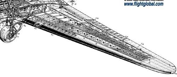
“In determining the wing construction of the early Douglas machines single, two, three and multi spar designs were considered as well as shell type and multi-cellular designs. After a thorough investigation of all types the Northrop multi-cellular wing construction was finally decided upon. This type of structure consists of a flat skin reinforced by numerous longitudinals and ribs. The bending is taken by the combination of flat skin and full length [longitudinal] stringers. Three main flat [vertical] sheets or ‘webs’ carry the shear loads. Torsion and indirect stress are carried by the skin with frequent ribs preserving the contour and dividing the structure up into a number of small rigid boxes or cells. Since the major loads are carried in the outer surface of the wing as well as in the in the internal structure, an inspection of the exterior gives a ready indication of the structural condition. The unit stresses in the material are low and therefore the deflections are at a minimum giving a maximum in rigidity. This construction has proven to be a happy medium of those considered since it combines practically all of the advantages of each; namely, very small unsupported areas, extreme lightness for its strength and rigidity; also ease of construction, inspection, maintenance and repair.“
For the early Douglas airliners:
“The Northrop wing being comparatively small, it is economical to have many of the stringers run from the top to the bottom of the wing as shear webs or spars. However, when the principle is carried out on a larger scale, as in the DC-1 with its deeper wing, it is more efficient to have only three shear webs or spars. Thus it was not necessary to evolve a new type of structure but merely to adapt a time proven type to the dimensions of the DC-1.” [end of quote]
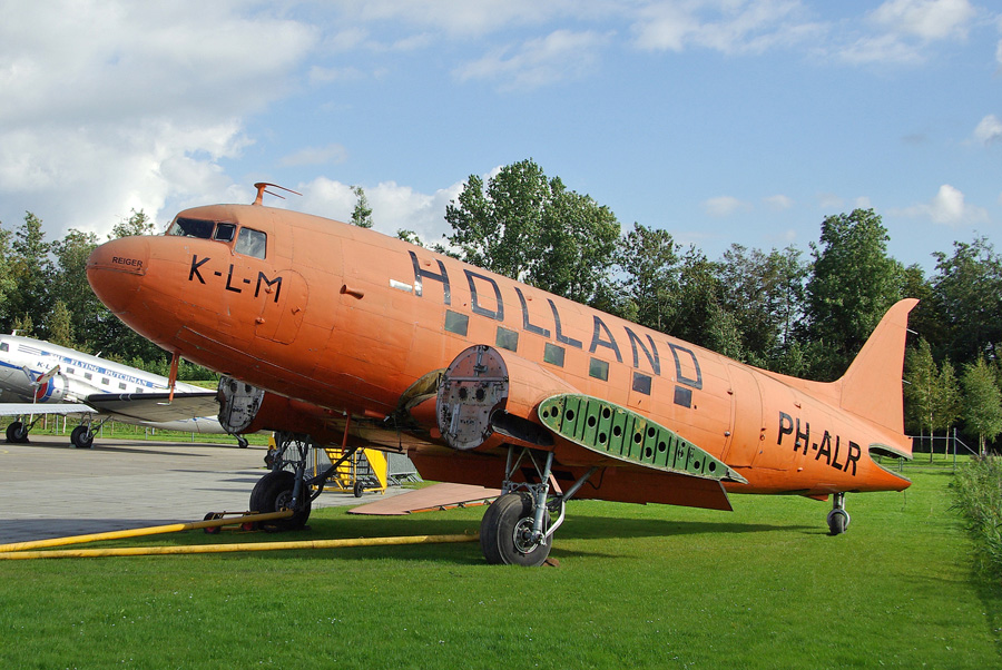
The exterior wing was fastened to the center section with a great numbers of bolts. It was my task to receive each bolt, nut and washer that became undone and secure them in a numbered hole in a plywood board. In the end there were 20 boards with a total of 652 bolt sets. My mentors /colleagues worked according to strict KLM protocol [see the following drawing which I owe to Mr. Wim Snieder, The Hague, Holland] and had the use of an overhead crane.

We finished unbolting the [half] wing by 3 pm and went for tea, delivering on our way the boards with fasteners at Testing for examination on hair cracks and corrosion.

Hello Billy
May I call you so?
Just saw your fabulous website with Northrop story – Very interesting in all its details.
I doubt if I can help you much more – you already found the quote from the Nat Air and Space Museum.
(I am a mechanical engineer by training, not an aerospace eng; I have followed aviation keenly as an amateur.)
So if there are specific questions, maybe I can be of help by finding sources, etc.
Great to know you!
Rit
rit_staalman@hotmail.com